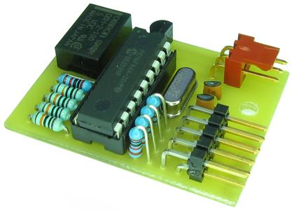
With this device you can control a video camera via LANC commands. The desing is based on David Meeds software and Viktor Carlquists hardware. I have made changes to the code and redesigned the schematic and pcb. Now you can turn the camera on with the same button you turn it off.
If you read the source code you will find a section where you can change the LANC codes to what ever you want. You have to change the byte 0 and 1. You can find LANC commands here. After editing you can assemble a .hex file with MPASM and flash it into the pic chip. There are plenty of DIY pic programmers and ready made ones on the internet.
Below you find a table for my assembled hex file (name of command and hex values). Some mystical bug causes that continuous commands (zoom, focus etc.) don't work on some places (marked grey).
LANC command table:
|
|
A |
B |
C |
D |
|---|---|---|---|---|
|
1 |
Power off |
WB toggle |
Focus near |
Zoom tele |
|
2 |
WB reset |
Backlight |
Focus far |
Zoom wide |
|
3 |
Menu |
Menu right |
Auto Focus |
Shutter |
|
4 |
Menu up |
Menu Down |
Exposure |
Rec/Pause |
Pins A-D and pins 1-4 forms a keyboard matrix. You can use different commands by connecting pins A-D to pins 1-4. Connecting pin C to pin 3 gives auto/manual focus command. You can use reed relays or some other switches. Combination A-1 turns the camera off. It also turns the camera on by hardware. It connects LANC to GND.
Connector pinout:
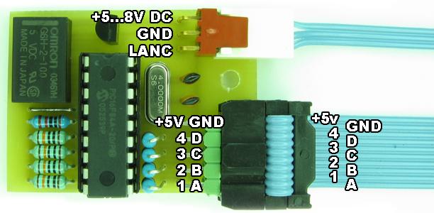
The
two upper pins of the pin-header are ground and +5V (when camera is
on). You can connect a led+ resistor to these or control monitor to
turn on/off etc. Use this for low current only.
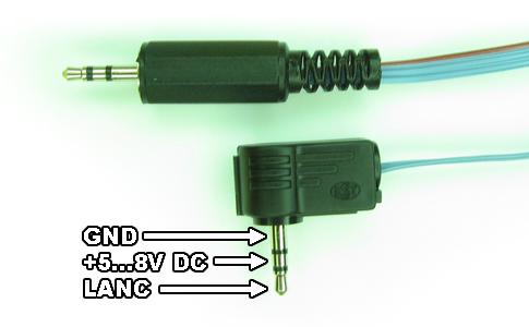
The LANC connector is a 2.5mm stereoplug.
Component layout (red line is a jumper wire under the ic):
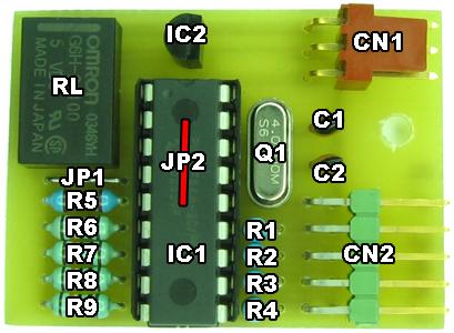
Parts list (links to
www.elfa.se):
•JP1-JP1 jumper wire
•R1-R5 10kΩ
•R6-R9
100kΩ
•CN1 3-pole Molex angled
•CN2 2*5
pin-header angled
•C1-C2 18pF
•RL Omron
G6H-2100-5
•IC1 PIC16F84A-04/P
+ DIL
socket
•IC2 LM78L05
•Q1 4MHz crystal low-profile
You also need:
•3-pin
Molex female
•flat-cable connector 10-pole
female
•flat-cable 10 and 3 pole
•2.5mm stereo male
plug
PCB image. Print 600dpi for correct size.
You can build your own controller or buy a ready build controller from me. I sell these for 50€. You may define cable length, straight or angled plug and LANC commands. The keyboard cable is 50cm by default. You have to add switches yourself.
Future plans:
•fix the bug for
continuous commands
•code a series of commands onto one
button (then you can change WB with one press of a button)
Coming soon (I hope): The rest of the DIY video housing.